How to cite: Xu S., Nieto-Samaniego, A.F., Xu, H., Li, W., Nieto-Fuentes. R., 2023, Quantitative determination of fault slip magnitude: a review: Revista Mexicana de Ciencias Geológicas, v. 40, núm. 1, p. 85-95.
REVISTA MEXICANA DE CIENCIAS GEOLÓGICAS
v. 40, núm. 1, 2023, p. 85-95
DOI: http://dx.doi.org/10.22201/cgeo.20072902e.2023.1.1728
Quantitative determination of fault slip magnitude: a review
Shunshan Xu1,*, Angel Francisco Nieto-Samaniego1, Huilong Xu2, Wei Li2, and Ricardo Nieto-Fuentes3
1 Centro de Geociencias, Universidad Nacional Autónoma de México, Campus Juriquilla, Blvd. Juriquilla 3001, Querétaro, C.P. 76230, Mexico.
2 South China Sea Institute of Oceanology, Chinese Academy of Sciences, st Xingang Road, Guangzhou, China.
3 Centro de Investigación en Matemáticas (CIMAT), Jalisco S/N, Col. Valenciana, Guanajuato, Gto., C.P. 36023, Mexico.
* sxu@geociencias.unam.mx
ABSTRACT
In geology, a fault is a rock fracture with perceptible relative displacement of the opposite sides of the fracture. Quantitatively obtaining the activity history of faults depends mainly on the estimation of fault slip and the study of markers, which can be used to understand and analyze the tectonic evolution of the faulted regions. Fault slip is calculated by restoring points that were originally adjacent before the deformation, those points are named piercing points. In this paper, we review some published methods to determine fault slip, using: (1) the offset of contours on structural contour maps; (2) offset on seismic reflection sections; (3) a known slip vector (fault striae) and one marker; (4) two known markers. Cases (3) and (4) are commonly applied to field work and geological maps.
Key words: fault slip; piercing points; fault separation; displacement vector.
RESUMEN
En Geología, una falla es una fractura en las rocas en donde se aprecia desplazamiento de los lados opuestos de la fractura. Determinar cuantitativamente la historia de actividad de las fallas descansa principalmente en la estimación del desplazamiento y del estudio de marcadores, los cuales pueden ser utilizados para entender y analizar la evolución tectónica de regiones deformadas por fallamiento. El deslizamiento de una falla es calculado restaurando a su posición original dos puntos que estuvieron adyacentes antes de la deformación, dichos puntos son llamados “puntos de referencia” (piercing points). En este trabajo presentamos una revisión de algunos métodos usados para determinar el desplazamiento de fallas: (1) usando el desplazamiento de los contornos en mapas de contornos estructurales; (2) utilizando secciones de sísmica de reflexión; (3) conociendo el vector de desplazamiento (estría de la falla) y un marcador; (4) conociendo dos marcadores. Los casos 3 y 4 son comúnmente aplicados en el trabajo de campo y en mapas geológicos.
Palabras clave: desplazamiento de falla; puntos de referencia; separación de falla; vector de desplazamiento.
Manuscript received: November 17, 2022
Corrected manuscript received: february, 16, 2023
Manuscript accepted: february 17, 2023
INTRODUCTION
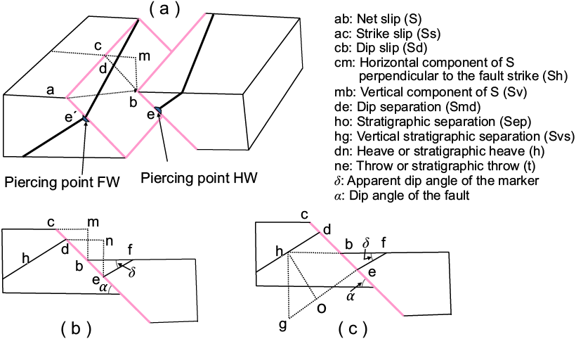
A fault is a fracture in rocks of the earth's crust along which there has been measurable relative displacement as a result of rock-mass movement parallel to the fracture surface (e.g. Tearpock and Bischke, 2003). The movements may occur in a single event or cumulatively in multiple events. Displacement may range from less than a centimeter to several hundred kilometers along the fault plane. Fault displacement is a general term for fault movement and describes the relative movement of two rock blocks along the fault plane measured in any specified direction (Reid et al., 1913; Tearpock and Bischke, 2003). The distinction between separation and slip is fundamental to the proper geometric and kinematic understanding of fault displacements. The slip of a fault is a measure of its true displacement. It is the relative displacement of formerly adjacent points on opposite sides of the fault, measured on the fault surface (e.g., Bates and Jackson, 1987; Waldron and Snyder, 2020). Typically, it has components parallel to dip (dip-slip) and parallel to strike (strike-slip), as shown in Figure 1. On the other hand, separation is the distance between two cutoff lines of a marker on a fault, measured in a specified direction on a fault surface. Similarly, the separation has components parallel to the dip (dip-separation) and parallel to the strike (strike-separation). If true slip cannot be determined, the displacement should be described as an apparent offset (fault separation).
The data of fault slip are often applied in many types of studies. (1) Fault classification is based on the type of fault slip (strike-slip fault, dip-slip fault, oblique-slip fault, etc.) (e.g., Ragan, 2009). (2) Large fault slips are used to assess the tectonic evolution of plate movements. (3) Fault slip is a key element in understanding fundamental deformation processes, for example, growth faults in three dimensions, the interaction between faults, and the spatial relationships between deformation and sedimentation. (4) Fault slip is used to conduct local or regional strain analysis (Jamison, 1989; Lavecchia et al., 2022). (5) The information of fault slip is helpful in the exploration of natural resources, such as ore deposits (e.g., McKinstry, 1948), and oil or gas (e.g., Evans et al., 1997).
There are several methods to determine fault slip. In this paper, we review some important quantitative methods in the following cases: (a) case of structural contour maps; (b) seismic reflection sections; (c) cases of known slip vector and one marker; (d) case of two known markers without a slip vector.

Figure 1. (a) Block diagram showing displaced surface by an oblique-slip fault. Detaied components of fault slip are shown. Pircing points in the hanging wall (HW) and footwall (FW) are marked. (b) Vertical cross-section perpendicular to the fault strike showing the dip-slip (cb) and dip-separation (de) and their components, respectively. (c) Vertical cross-section perpendicular to the fault strike showing the vertical stratigraphic separation (hg or Svs).
TERMINOLOGY OF FAULT DISPLACEMENT
Extensive terminology has developed around faults, their geometry and kinematics (Figure 1). The different terms mostly refer to different frames of reference of the slip vector.
Net slip is the line on the fault surface that connects two points that were together before deformation (ab or ee' in Figure 1a). These two points are called “piercing points”. When the pitch of the slip is near 0°, close to the strike of the fault, the fault is called a strike-slip fault. Strike slip is the strike-parallel slip component (ac in Figure 1a). When the pitch of the slip is near 90°, close to the dip of the fault, the fault is a dip-slip fault. The dip slip (cb) can be resolved into two components. One is the horizontal component perpendicular to the fault strike (cm in Figures 1a, 1b), and another is the vertical component (mb in Figures 1a, 1b). Oblique faults are defined by combinations of dip-slip and strike-slip. Thus, the oblique-normal and oblique-reverse faults that also have components of right-lateral (right-handed) or left-lateral (left-handed) slip.
In map view, strike separation is defined as the distance along a fault trace, measured in the direction of fault strike, between two cutoff lines of the same truncated surface. The strike separation can be sinistral (left-lateral) or dextral (right-lateral). In cross-section view, dip separation is the distance along a fault plane, measured in the direction of fault dip, between two cutoff lines of the same truncated surface (de in Figures 1a, 1b). If the beds in the hanging wall are offset below those in the footwall, the separation is normal. If the beds in the hanging wall are offset stratigraphically above those in the footwall then the separation is reverse (Lisle, 2004; Ragan, 2009). The vertical and horizontal components of dip separation were very important in old mining operations and are known as throw (ne in Figure 1b) and heave (dn in Figure 1b). It is important to understand that throw (ne) and vertical slip (mb) are different. The throw is not normally used in subsurface mapping techniques.
The stratigraphic separation is the perpendicular distance between a (subparallel) stratigraphic surface on opposite sides of a fault (ho in Figure 1c). If the separation is measured vertically, the distance is called vertical separation (hg in Figure 1c). Vertical separation is the difference in height between the displaced geological surface in the hanging and footwalls, calculating from structure contour maps (Lisle, 2004). The throw and vertical separation are readily confused. Sometimes, vertical separation is called throw, or throw is substituted for vertical separation (Subsurface Consultants & Associates, 1993).
METHODS TO DETERMINE FAULT SLIP
Piercing points
A line that is cut and displaced by the fault defines two points that were adjacent before displacement. With those initially adjacent points, called piercing points, the slip vector can be uniquely solved (Figure 1a). Adjacent points may move apart in any direction parallel to the fault surface. The piercing point on the hanging wall is called hanging wall piercing point, and that on the footwall is called footwall piercing point. Planes offset by a fault on typical block diagrams are not piercing points and hence cannot be used to measure slip.
Many kinds of displaced lines can be found to determine and calculate the net slip or its components. (1) Two features with the same age on opposite sides of the fault allowing geologists to reconstruct how much motion there must have been for the large strike-slip faults (e.g., Cather 1999). These features can be sedimentary units, intrusive bodies, orogenic belts, basins, facies changes, and paleo-shorelines (Cather et al., 2006; Waldron and Snyder, 2020); (2) Linear features such as fences, stream channels, roads, etc., that are offset by surface ruptures in earthquakes (Rockwell, 1988; Avouac and Tapponnier, 1993; Lavé and Avouac, 2000); (3) Constructed lines, such as isopachs, lithofacies lines, and traces of axial surfaces with bedding (e.g., Crowell, 1959).
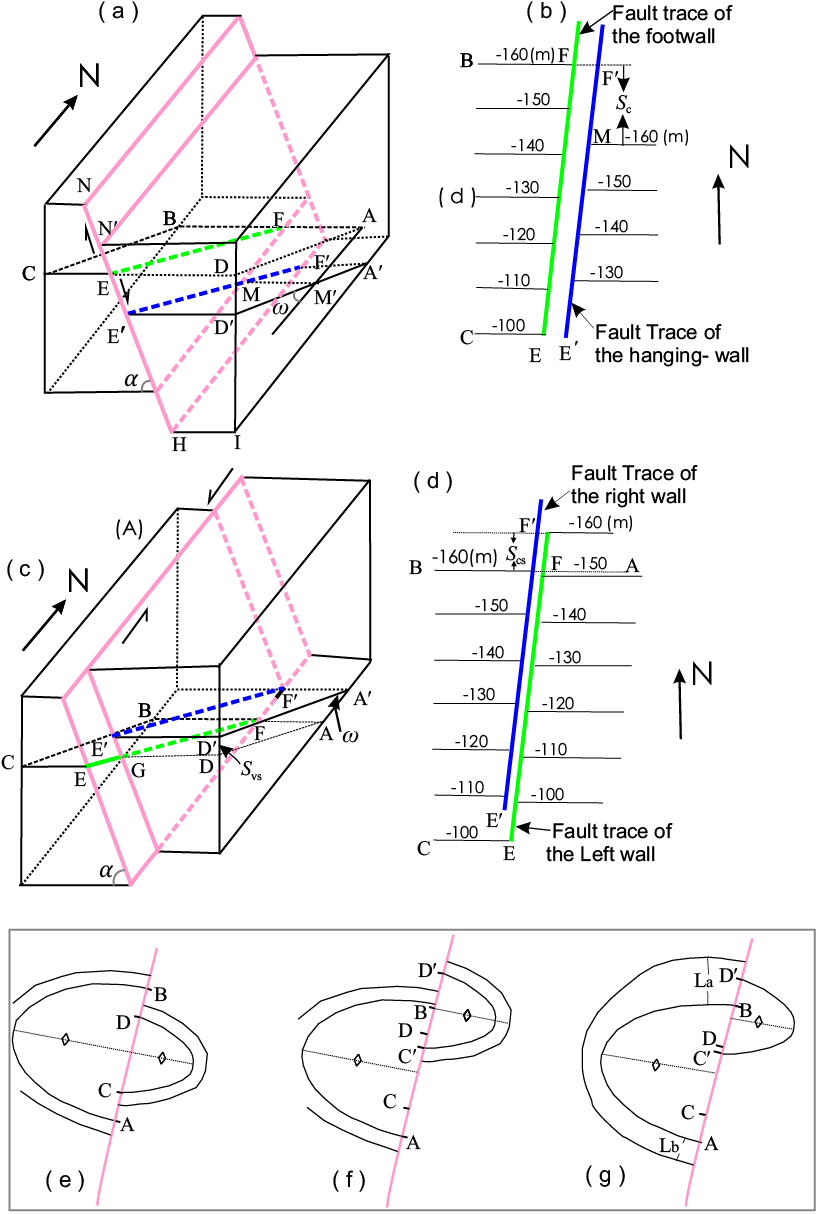
Figure 2. Diagrams showing fault offset contours in three cases (Modified from Xu et al., 2004). (a). The right part (AFED) of the bed plane is moved to the location of AʹFʹEʹDʹ due to the dip-slip of the fault. The vertical slip component (Sv) of the fault is DDʹ. (b). Supposed structure contour map of the bed from block diagram (a). Offset (Sc) contours occurred after the slip of the fault. The offset (Sc) of the contour can be estimated by Sv /tanβ from (b). Note that the value of Sc is none of the slip components of the fault. The coarse red lines are the fault traces on the contour map. (c). The fault has only strike slip. After faulting, the line AF is moved to the location of AʹFʹ. (d). Supposed structure contour map from (c). The offset (Scs) of contours is equal to the strike-slip of the fault. The vertical offset of the bed is not the true fault slip. The coarse red lines are the fault traces on the contour map. (e)–(g) show offsets of contours on a map that shows a fault intersecting a fold. (e) Fault without strike-slip results in the same offset in the two limbs of an upright symmetric fold. (f) Fault with a lateral slip component results in different offsets in the two limbs of an upright symmetric fold. (g) Fault with a lateral slip component causes different offsets in the two limbs of an asymmetric fold.
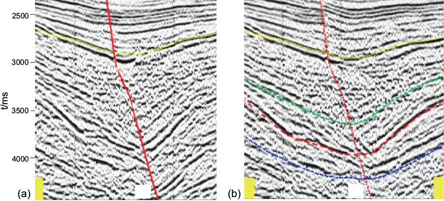
Figure 3. Example for determination of strike slip using fault-perpendicular seismic reflection profiles (modified from Mu and Zhao, 2021). (a) An arbitrarily profile selected perpendicular to the strike-slip fault. Two parts are designed: Hanging wall (right) part and footwall (left) part. (b) The hanging wall from another profile is spliced to the footwall in (a).
Determination of fault slip of subsurface faults
Methods using subsurface structural contours
The problem of actually measuring fault slip in the subsurface can sometimes be overcome by using subsurface structural contour maps constructed from well logs and seismic information. These maps are useful for estimating fault slips since the fault motion will cause the offset of contours to occur. The offset of contours is here defined as the distance in the fault strike direction between two contours of the same value on opposite sides of a fault (Sc in Figure 2b). The methods for calculating the fault slip are presented by Xu et al. (2004):
(a) In the case of a displaced bed
If a pure dip-slip fault displaces a tilted bed, the offset (Sc) of contours can be estimated from the vertical component (Sv) of the fault slip, according to the following relationship: Sv= Sc tanω, where ω is the dip angle of the bedding (Figures 2a, 2b). As a result, the dip-slip (Sd) can be estimated as:
Sd = Sv /sinα = Sc tanω/sinα . (1)
Where α is the dip angle of the fault.
On the other hand, if a strictly strike-slip fault displaces a tilted bed (Figures 2c, 2d), the offset (Scs) of contours is equal to the strike-slip of the fault (Ss),
Ss = Scs . (2)
(b) In the case of displaced fold
Both symmetric and asymmetric cases are considered.
In the case of a symmetric upright fold (Figure 2f), the strike component (Scs) of fault slip is calculated by the equations
Scs= (Smax + Smin) / 2 (3)
where Smax is the larger total offset (Sc+Scs) of a contour line between the two limbs of the fold, and Smin is the smaller total offset (Sc–Scs) for the same contour line. In this case, Sd can also be calculated by using the equation:
Sd= (Smax – Smin) tanω/2 sinα (4)
Similarly, for an asymmetric fold (Figure 2g), the strike-slip component is expressed by:
Ss= Scs= (n Smin + Smax)/(n + 1) (5)
where n is the ratio between the distances of interlines of the two limbs, and n>1.
For n>1 (n=La/Lb), the dip slip can be written as
Sd = (Smax – Smin) tanωb/(n + 1) (6)
For n< 1 (n = Lb/La, where La, and Lb are the distance between two contour lines of limb a and limb b), the dip slip can be
Sd = (Smax – Smin) tanωa/(n + 1) (7)
Where ωa, and ωb are the dip angles of limb a and limb b, respectively.
Determination of strike slip using seismic reflection profiles
The seismic reflection method provides the highest resolution images of the structure of the crust and Moho across scales and tectonic settings (e.g., Martí et al., 2008). Previous authors propose two methods to determine the strike slip of a strike-slip fault by using seismic reflection profiles (Mu and Zhao, 2021). The first method is the scanning splicing method of seismic profiles. For this method, a seismic profile perpendicular to a strike-slip fault is arbitrarily selected as the initial profile (Figure 3a), and the left half of the fault is taken as a comparison. The right half of the fault from other parallel profiles is spliced with the left half until the closest match profile is found, for which no stratigraphic displacement appears (Figure 3b). Then, the distance between the two matching profiles is the strike slip.
Another method is the comparison of reflection characteristics of parallel seismic profiles on both sides of the fault. Two fault-parallel profiles adjacent to the fault are aligned according to their geographic positions to find characteristic points or displaced points. The two profiles are assigned left and right, respectively (Figure 4). In this figure, the characteristic points (piercing points) showing in blue circles are the stratigraphic discontinuity points A and Aʹ. The horizontal distance between two points A and Aʹ with the same characteristics is the strike slip of the fault. The strike slip in the example of Figure 4 is 375 m.
Case of knowing slip direction and one separation on a fault
Usually, we only have information on displaced planes, such as bedding planes, unconformities, dikes, sills, contacts, etc., and lack recognizable lines within these planes. Thus, if the information of only one marker is obtained, the fault slip cannot be calculated (e.g., Hill, 1959). When the fault separation and slickenside lineations on a fault are known, the magnitude of net slip can be estimated. The methods applied in this case are not appropriate for reactivated faults, because slickenside lineations preferentially tend to record the final slip events. The geometrical model assumes that (Xu et al., 2007; Nieto-Fuentes et al., 2014): (a) The faults are planar. Faults are seldom flat surfaces, but rather than curved geometries due, among other factors, to the heterogeneities of the environment, the linkage of fault segments and the interference of other structures. (b) Slickensides are straight and are parallel to the net displacement vector. (c) there is no displacement perpendicular to the fault plane. (d) The host rock is a rigid body, so there is no strain within the blocks. (e) The slip is constant in the measurement region. In general, these conditions hold depending on the scale of analysis; competent rocks most likely fulfill the requirements of the geometric models in scales from decimeters to several hundred meters at shallow crustal levels. Diverse solutions have been proposed for calculating the net slip: graphic methods (Ragan, 2009; Babín-Vich and Gómez-Ortiz, 2010; Lisle and Walker, 2013; Waldron and Snyder, 2020), simple trigonometric equations (Xu et al., 2007; Nieto-Fuentes et al., 2014) and vector equations (Yamada and Sakaguchi, 1995; Nieto-Fuentes et al., 2022).
An example of graphic method is shown in Figure 5. We constructed the stereogram by projecting the fault and the bed (marker) (Figure 5b). The point of intersection of the major circles represents the trace of the bed in the fault plane (cutoff line of the bed on the fault, seen in the fault plane). To determine the magnitude of the net displacement, we need to construct a section parallel to the fault plane. In this section, all lines in the fault plane can be represented by measured pitch angles relative to the fault strike line (β in Figure 5b). This angle for the bed is measured directly on the stereogram, taking the great circle that represents the fault plane to the N-S diameter of the stereonet and counting the corresponding angle with the help of the small circles. The distance along the slickenline on the fault projection is the net slip of the fault (Figures 5c–5f).
There are some subcases for trigonometric methods. For cases where only the strike separation or the dip separation is measured, we still need the pitch of slip lineations (γ), the pitch of a cutoff (β), the dip separation (Smd) or the strike separation (Smh) for one marker. We consider two different scenarios according to different types of data that may be available.
1). Slickenside striations with opposite pitch direction to marker traces.
If the dip separation (Smd) is measured, we considering the triangle CEC’ in Figure 6, we can see that CCʹ/sin (90–β) = ECʹ/sin(γ+β). Since CCʹ=S and ECʹ=Smd; then,


(8)
For the strike separation of the marker (Smh = FBʹ in Figure 6) and following a similar procedure, the fault slip will be

(9)
2). Slickenside striations with the same pitch direction as marker traces
For the case where β > γ, two equations to calculate the fault slip are written as

(10)

(11)
For the case where < γ, the equation to calculate the fault slip is written as:

(12)
On the other hand, if the separation is measured from an arbitrary observation line (Xu et al., 2009), the parameters for calculation are the pitch of slip lineation (γ), the pitch of a cutoff (β), the apparent displacement along the observation line (Sm), and the pitch of the observation line on the fault plane (φ). The equations using an arbitrary observation line are shown in Table 1.
A more simple method by using vector equations to determine fault slip is described by Nieto-Fuentes et al. (2022). For the case when slip lineation is known, the net displacement is the intersection of the slickenline vector with the displaced marker plane, the function used for obtaining it is , (13)

where ˆl O is the unit vector parallel to the observation line, Sm is the apparent displacement along the observation line, M the unit vector normal to the marker and 𝔰ˆ the unit vector (direction vector) of the slickenline (complete explanation and computer program is described in Nieto-Fuentes et al., 2022). The net slip is

.
Two non-parallel markers displaced by a fault
There are graphic methods (Ragan, 2009; Babín-Vich and Gómez-Ortiz, 2010; Lisle and Walker, 2013; Waldron and Snyder, 2020) and methods of vector equations (Yamada and Sakaguchi, 1995; Nieto-Fuentes et al., 2022) to determine the fault slips when two non-parallel planar markers are known.
The steps of graphic methods are shown in Figure 7. (1) In the stereogram, we determine the pitch angles of the two markers on the fault plane (Figure 7b), the markers are the two displaced faults. (2) The traces that pass through points A and B intersect at point X. Those that pass through Aʹ and Bʹ intersect at point Y. Note that the traces corresponding to the markers are parallel on both blocks of the fault, meaning there was no rotation (Figure 7c). (3) The distance XY is the net slip. The vector  is the slip vector. Along an arbitrary observation line, three parameters can be measured (Sma, Sab, Smb in Figure 7d). By using these parameters, we also can determine the net slip.
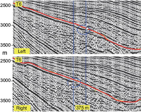
Figure 4. Example for determination of strike slip using fault-parallel seismic reflection profiles (modified from Mu and Zhao, 2021).Two fault-parallel profiles adjacent to the fault are aligned according to their geographic positions to find characteristic points (piercing points). In this figure, characteristic points are the stratigraphic discontinuity point A and Aʹ, respectively.
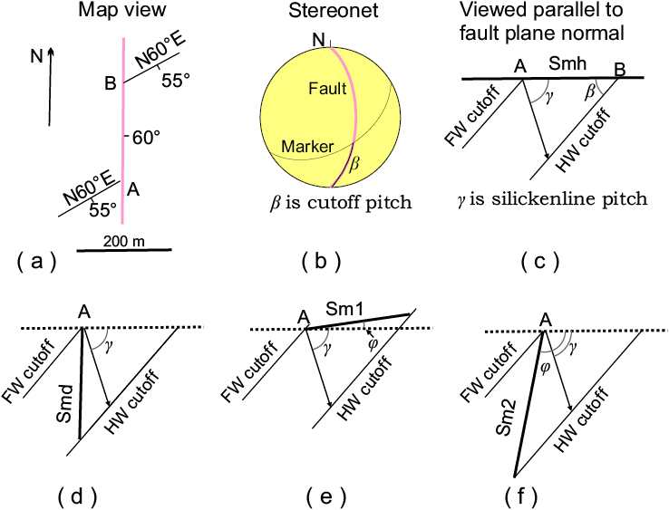
Figure 5. Example of determining fault slip in the case of knowing the slip vector and one marker. (a) Geological map. (b) Stereogram. (c) Determination of the fault slip when knowing the strike-separation and slip vector on the fault plane. (d) Determination of the fault slip when knowing the dip-separation and slip vector on the fault plane. (e) and (f). Determination of the fault slip when knowing an arbitrary separation and slip vector on the fault plane. γ pitch angle of the slip, β pitch angle of the cutoff of the marker, φ pitch angle of the observation line.
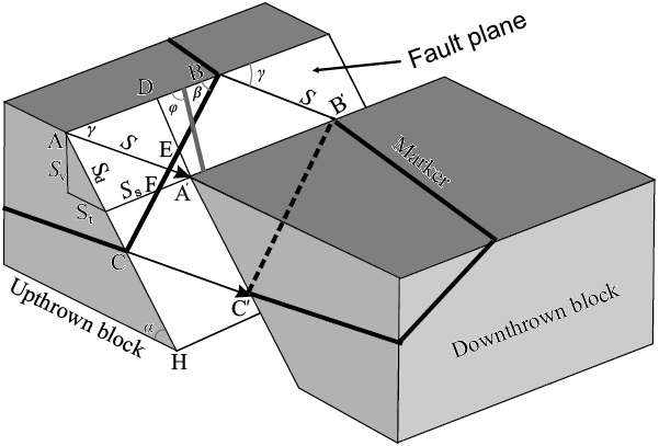
Figure 6. Block diagram showing a marker displaced by a lateral-normal-slip fault. S, net slip; Sd, dip-slip; St, true heave; Sv, vertical component the net slip; Ss, strike-slip component; γ, pitch angle of the slip; β, pitch angle of the cutoff of the marker, φ pitch angle of the observation line; ECʹ Smd, dip separation; and FBʹ Smh, strike separation are known.
The separation-pitch diagram proposed by Lisle and Walker (2013) is also used to estimate fault slip from map data. This method can be also applied in arbitrary case that is shown in Figure 7. In the case of one marker and the slip direction, if a separation in any direction on the fault (Sa1) is known, the net slip can be measured as shown in Figure 8a. On this graph, the point in the measured direction is determinated by the measured separation Sa1 and the angle of pitch of the marker, with the slip sense considering the viewing direction (γa). The drawn line is called the solution line, which represents a possible solution for the net slip of the fault (Lisle and Walker, 2013). Net displacement is the distance from end of Sa1 and the solution line, measured in the slip direction. Similarly, in the case of two markers, two separations along a direction on the fault (Sa1 and Sb1) are known, the intersection point of two cutoffs determine the slip direction and the net slip (Figure 8b).
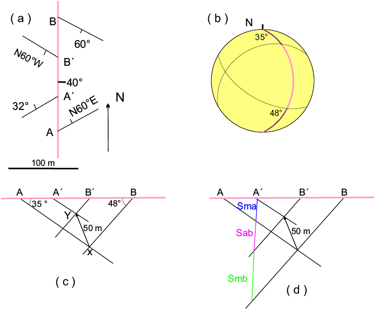
Figure 7. Example of determining fault slip in the case of obtaining two markers. (a) Geological map. (b) Stereogram. (c) Determination of the fault slip when knowing the strike-separations on the fault plane. (d) Determination of the fault slip when knowing arbitrary separations on the fault plane.
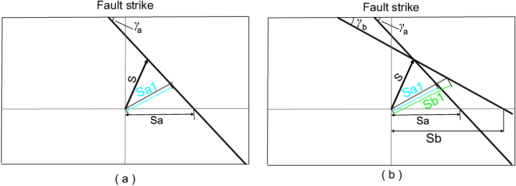
Figure 8. The separation-pitch diagrams to estimate the net slip. (a) The case with the slip direction. The separation on the fault (Sma1) and the slip direction are known. The net slip is measured along the slip direction. (b) In the case of two markers, two separations along a direction on the fault (Sma1 and Smb1) are known. The net slip is determined by the intersection point of two cutoffs.
For the case without slip lineation, in which two markers are needed, a simpler method by using a vector equation for a non-rotation case is presented by Nieto-Fuentes et al. (2022). Considering that three planes mutually intersect in a point, the intersection of the fault plane and the two markers is calculated in the hanging block and in the foot block. One of them is considered pre-deformation (ι) and the other post-deformation (ι’). The function for calculating the intersection is

, (14)
where Ma is the unit vector perpendicular to the first marker plane (a), p→a a point on the marker a, Mb the unit vector perpendicular to the second marker plane (b), p→b a point on the marker b, f the unit vector perpendicular to the fault plane and p→f the point on the fault plane. Then, the distance between the pre- and post- deformation points is the net displacement of the fault:

, (15)
The subscripts A, and B and F indicate the marker plains, and F the fault plane. ˆl 0 is the direction of the observation line, SmA and SmB are the apparent displacements. (complete explanation and computer program is presented in Nieto-Fuentes et al., 2022).
If the fault involves a rotation of one block relative to the other, the two displaced half-planes may not be parallel. Babín-Vich and Gómez-Ortiz (2010) give an example of the case of block rotation (Figure 9). A N30°W/40°E orientation fault cuts a stratum and a dike. The orientations of the bed and dyke are N20°E/30°W and N80°E/60°S on the footwall of the fault, whereas they are S60°E/28°E and N50°E/80°E on the hanging wall (Figure 9a). The pitch angles of the bed and dike traces on both blocks on the fault are calculated from the stereogram. We pass this information to a plane parallel to the fault plane, placing each of the elements in their appropriate position (Figure 9b). The XY line results from the union of the bed and dike intersections on both blocks of the fault; therefore, it represents the net displacement of the fault, whose magnitude measured at scale is 370 m. The orientation of this net displacement is given by the pitch of the line measured on the fault plane, which turns out to be 18°S.
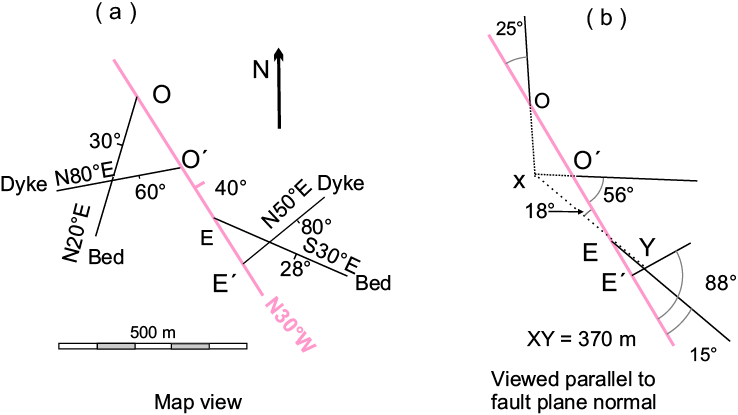
Figure 9. Example to determine fault slip in the case of two markers not- parallel on the two sides of the fault. (a) Geological map. (b) Plane map on the fault surface.
Figure 10. (a) and (b) Pressure solution produces apparent slip (Sp) (Modified from Billi 2003) (c) If a fault has a further opening AʹAʹʹ, the directly measured offset for the marker is CCʹʹ. This value is not equal to CCʹ. In this case, the value of St (CCʹ) cannot be directly measured (Modified from Xu et al., 2009).
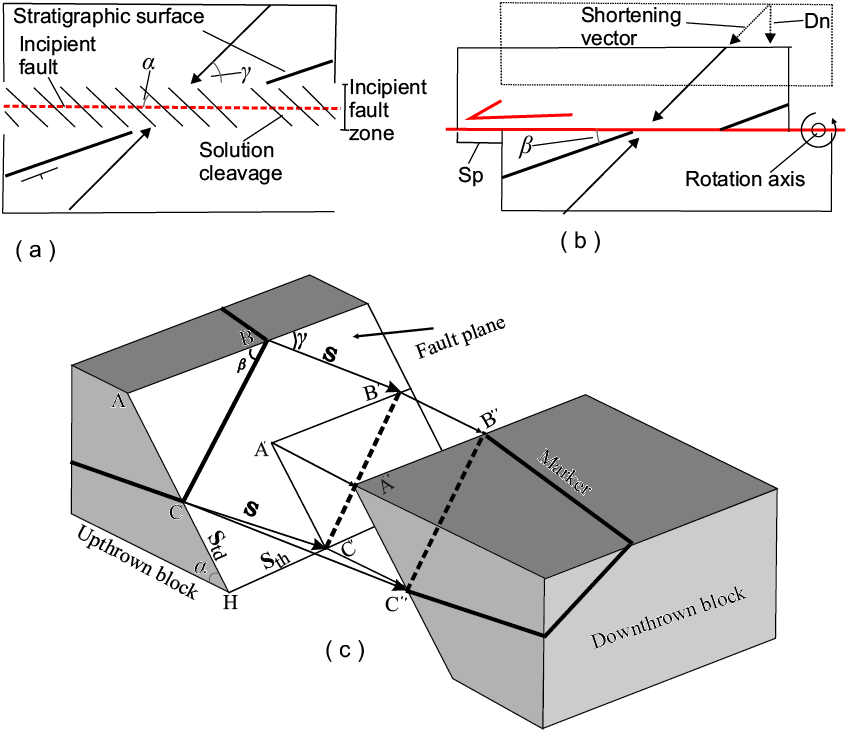
Table 1. Equations for calculation of net fault slip in the case of arbitrary observation line on the fault. Sm is the measured displacement of markers along the measured line on the fault. The parameter φ indicates the pitch of the observation line on the fault plane in different cases, also see Figuress 5e, 5f and figures 1, 4 of Xu et al., 2009).
|
Case 1: slickenside lineation with pitch direction opposite to that of marker traces. |
Case 2: slickenside lineation with the same pitch direction as that of marker traces. |
|
|
Case 1a: the observation line with the same pitch direction as the slickenside lineation. 
Case 1b: the observation line with the opposite pitch direction to that of the slickenside lineation. For 
For 
|
Case 2a: the observation line with the same pitch direction as the slickenside lineation. |
Case 2b: the observation line with the opposite pitch direction to the slickenside lineation. |
|
Case 2a-a: β > γ For φ > β 
For φ< β 
Case 2a: β < γ For φ > β 
For φ < β 
|
Case 2b-a: β > γ 
Case 2b-b: β < γ 
|
|
DISCUSSION
Each method of estimation of fault slip has its limitations and assumptions. Due to the different processes of obtaining fault data for a given fault, the results could be diverse based on various methods used by other researchers.
The net slip on the scale of the area from which the separation data are collected is required to be constant. However, numerous detailed fault studies show C-type or M-type distribution of slip across fault surfaces in terms of magnitude (e.g., Muraoka and Kamata, 1983). The slip in the fault center reaches maximum magnitude. The methods are, therefore, subject to errors when the strike separations are recorded at different positions along the fault trace. Fault linkage may increase fault slip gradient near the fault tips (e.g., Peacock and Sanderson 1991), which would produce more error of slip calculation .
In map view, the strike separation cannot generally be measured directly from a map. The distance measured from the map is a function of height differences between the cutoff points. A correction projecting planes or lines which are inclined to the same level is needed (Śmigielski et al., 2011; Lisle and Walker, 2013).
There are two special cases in which it is not possible to calculate the real displacement of the fault, since no apparent displacement is observed (Nieto-Fuentes et al. 2014), these are: (a) when the angle 𝜃=0° (angle between the slicklines and the cutoff of the marker), under these conditions the marker does not experience displacement observable because it is parallel to the fault striae, and (b) when the angle 𝜃𝑛=0° since the traces of the observation line and the marker are parallel, both on the fault plane, no displacement will be observed.
The errors will become very large as 𝜃 and 𝜃𝑛 approach 0°, so we strongly suggest not considering those calculations that obtain values of 𝜃<20° or 𝜃𝑛<10° as adequate.
SUMMARY
Fault slip magnitude is a geometrical attribute of faults of fundamental importance. It can relate to the fault's kinematic characteristics and hence indirectly to the stresses that produced the fault movement. Faults are not only the channel for the vertical migration of oil and gas but also control the formation and evolution of many oil and gas traps. Fluid passing through rocks may deposit valuable minerals. Faults are also important to humans because they are related to earthquakes. Theoretically, fault slip is calculated by restoring piercing points to their pre-offset locations. In this review, we described some published methods to determine fault slip magnitude as follows.
(1) Methods by using subsurface structural data
The methods include the cases of displaced fold and displaced bed. In the case of displaced bed (Figures 2a, 2b), the vertical component (Sv) of the fault slip can be estimated from the offset (Sc) of contours by the equation Sv = Sc tanω. The dip-slip (Sd) of the fault can be estimated as Sd = Sv/sinα = Sc tanω/sinα. In the case of a displaced symmetric fold (Figure 2f), the strike component (Ss) of the fault slip is calculated by the equations Ss= (Smax+Smin) / 2 and the dip slip (Sd) can be calculated by the equation Sd= (Smax-Smin) tanω/2 sinα. In the case of a displaced asymmetric fold (Figure 2g), the strike-slip component is expressed by Ss= (n Smin+Smax)/(n + 1).
(2) Methods by using seismic reflection sections
There are two methods. The first one is based on the scanning and splicing of the seismic profiles perpendicular to the fault strike. The distance between the two matching perpendicular profiles is the strike slip. The second one is to compare the reflection characteristics of seismic profiles parallel to the fault strike. The characteristic points are considered as piercing points. The horizontal distance along the profile strike of two characteristic points is the strike slip of the fault.
(3) Methods in the cases where the slip vector and one marker or two markers are known
For the graphic methods, a stereonet diagram and a diagram viewed parallel to fault normal are necessary. For the trigonometric methods, there are two different scenarios: a) slickenside striations with opposite pitch direction to marker traces; b) slickenside striations with the same pitch direction as marker traces. The vector method is a simpler and more general method.
ACKNOWLEDGEMENTS
This investigation was partially supported by the projects PAPIIT IN102020 of UNAM and 2020B1515020016 of Guangdong Nature Fund, China. The pertinent comments from Gustavo Tolson and anonymous reviwer are appreciated.
REFERENCES
Avouac, J.P., Tapponnier, P., 1993, Kinematic model of active deformation in central Asia: Geophysical Research Letters, 20(10), 895-898, https://doi.org/10.1029/93GL00128
Babín-Vich, R.B., Gómez-Ortiz, D., 2010, Problemas de Geología Estructural. 8. Fallas: Reduca (Geología), Serie Geología Estructural, 2(1), 124-147, URL: http://www.revistareduca.es/index.php/reduca-geologia/article/view/141
Bates, R.L., Jackson, J.A., 1987, Glossary of Geology, third ed.: Alexandria, Virginia, USA, American Geological Institute, 788 pp.
Billi, A., 2003, Solution slip and separations on strike-slip fault zones: theory and application to the Mattinata Fault, Italy: Journal of Structural Geology, 25(5) 703-715.
Cather, S.M., 1999, Implications of Jurassic, Cretaceous, and Proterozoic piercing lines for Laramide oblique-slip faulting in New Mexico and rotation of the Colorado Plateau: Geological Society of America Bulletin, 111, 849-868.
Cather, S.M., Karlstrom, K.E., Timmons, J.M., Heizler, M.T., 2006, Palinspastic reconstruction of Proterozoic basement-related aeromagnetic features in north-central New Mexico: Implications for Mesoproterozoic to late Cenozoic tectonism: Geosphere, 2(6), 299-323.
Crowell, J.C., 1959, Problems of fault nomenclature: American Association of Petroleum Geologists Bulletin, 43, 2653-2674.
Evans, J.P., Forster, C.B., Goddard, J.V., 1997, Permeability of fault-related rocks, and implications for hydraulic structure of fault zones: Journal of Structural Geology,19, 1393-1404.
Gasperini, L., Ligi, M., Polonia, A., Ferrante, V., Bonatti, E., 2003, Segmented, pull-apart fault system in the Gulf of Izmit: evidence from seismic reflection profiles: Geophysical Research Abstracts, 5, 11506.
Hill, M.L., 1959, Dual classification of faults: American Association of Petroleum Geologists Bulletin, 43, 217-221.
Jamison, W.R., 1989, Fault-fracture strain in Wingate Sandstone: Journal of Structural Geology, 11(8), 959-974.
Lavé, J., Avouac, J.P., 2000, Active folding of fluvial terraces across the Siwaliks Hills, Himalayas of central Nepal: Journal of Geophysical Research: Solid Earth, 105(B3): 5735-5770, https://doi.org/10.1029/1999JB900292.
Lavecchia, G., Bello, S., Andrenacci, C., Cirillo, D., Ferrarini, F., Vicentini, N., de Nardis, R., Gerald Roberts, G., Brozzetti. F., 2022, Quaternary fault strain Indicators database - QUIN 1.0 - first release from the Apennines of central Italy: Scientific Data 9, 204, https://doi.org/10.1038/s41597-022-01311-8.
Lisle, R.J., 2004, Geological Structures and Maps: A Practical Guide: Oxford, UK, Elsevier Science. 125 pp.
Lisle, R.J., Walker, R.J., 2013, The estimation of fault slip from map data: The separation pitch diagram: Tectonophysics, 583, 158-163, http://dx.doi.org/10.1016/j.tecto.2012.10.034
Martí, D., Carbonell, R., Flecha, I., Palomeras, I., Font-Capó, J., Vázquez-Suñé, E., Pérez-Estaún, A., 2008, High-resolution seismic characterization in an urban area: Subway tunnel construction in Barcelona, Spain: Geophysics, 73, B41–B50, 200.
McKinstry, H.E., 1948, Mining Geology: New York, Prentice-Hall, 680 pp.
Mu, X., Zhao, H., 2021, Identification of concealed strike-slip fault and estimation of strike-slip offset: A case study of the Jiyang Depression in Bohai Bay Basin: Geophysical Prospecting for Petroleum, 60(1), 57G166.
Muraoka, H., Kamata, H., 1983, Displacement distribution along minor fault traces: Journal of Structural Geology, 5, 483-495.
Nieto-Fuentes, R., Nieto-Samaniego, Á.F., Xu, S.-S., Alaniz-Alvarez, A., 2014, Software for determining true displacement of faults: Computers and Geosciences, 64(1), 35-40, http://dx.doi.org/10.1016/j.cageo.2013.11.010.
Nieto-Fuentes, R., Nieto-Samaniego, Á.F., Xu, S.-S., Alaniz-Alvarez, A., 2022, TruDisp 2.0 una aplicación para el cálculo del desplazamiento verdadero (neto) en fallas: Revista Mexicana de Ciencias Geológicas, Sección Especial "20 años del Centro de Geociencias, UNAM", 39(3), 285-292, doi: http://dx.doi.org/10.22201/cgeo.20072902e.2022.3.1705.
Peacock, D.C.P., Sanderson, D., 1991, Displacements, segments linkage and relay ramps in normal fault zones: Journal of Structural Geology 13, 721-733.
Ragan, D.M., 2009, Structural Geology: An Introduction to Geometrical Techniques, 4th ed.: New York, USA, Cambridge University Press, 602 pp.
Reid, H.F., Davis, W.M., Lawson, A.C., Ransome, F.L., Committee, 1913, Report of the committee on the nomenclature of faults: Geological Society of America Bulletin, 24, 163-186.
Rockwell T, 1988, Neotectonics of the San Cayetano fault, transverse ranges, California: Geological Society of America Bulletin, 100(4), 500-513, https://doi.org/10.1130/0016-7606(1988)100<0500:NOTSCF>2.3.CO;2
Śmigielski, M., Koprianiuk, M., Konon, A., 2011, Determination of fault displacement vector parameters based on strike separation: Przeglad Geologiczny, 59(1), 74-81.
Subsurface Consultants & Associates, Inc., 1993, Quick look techniques: mapping throw in place of vertical separation: A costly subsurface mapping misconception: Houston Geological Society Bulletin, 36(4), 56-57.
Tearpock, D.J., Bischke, R.E., 2003, Applied subsurface geological mapping with structural methods, second ed. Prentice Hall PTR, 822 pp.
Xu, S.-S., Velasquillo-Martinez, L.G., Grajales-Nishimura, J.M., Murillo-Muñetón, G., García-Hernández, J., Nieto-Samaniego, A.F., 2004, Determination of fault slip components using subsurface structural contours: methods and examples: Journal of Petroleum Geology, 27, 277-298.
Xu, S.-S., Velasquillo-Martinez, L.G., Grajales-Nishimura, J.M., Murillo-Muñetón, G., Nieto-Samaniego, A.F., 2007, Methods for quantitatively determining fault displacement using fault separation: Journal of Structural Geology, 29, 1709-1720.
Xu, S.-S., Nieto-Samaniego, A.F., Alaniz-Álvarez, S.A., 2009, Quantification of true displacement using apparent displacement along an arbitrary line on a fault plane: Tectonophysics, 467, 107–118.
Xu, S.-S., Nieto-Samaniego, A.F., Alaniz-Álvarez, S.A., 2013, Origin of superimposed and curved slickenlines in San Miguelito range, Central Mexico: Geolgica Acta 11(1), 103-112. https://doi.org/10.1344/105.000001760
Yamada, E., Sakaguchi, K., 1995, Fault-slip calculation from separations: Journal of Structural Geollogy, 17, 1065-1070.
Waldron, J.W.F, Snyder, M., 2020, Geological structures: a practical introduction: University of AlbertA, Open Education Alberta, 225 pp. https://open.umn.edu/opentextbooks/textbooks/899.